
Cathodic protection helps control corrosion on buried pipelines, storage tanks, offshore structures, and other metal assets. In 2026, selecting the right Impressed Current Anode means looking beyond product names and headline output ratings. The anode must suit the structure, surrounding soil or water, electrical demand, and available power supply. A mismatch can lead to uneven protection, avoidable maintenance, or a system that performs poorly over time.
Anode materials such as mixed metal oxide, high-silicon cast iron, and graphite serve different conditions. Their expected service life depends on current density, electrolyte properties, installation quality, and operating controls. A design review should consider coating condition, anode-bed layout, cable connections, rectifier settings, and monitoring access. These details matter in the field. A loose connection, for example, can disrupt current distribution even when the anode itself is correctly specified.
No single anode wins everywhere. That is the useful, slightly inconvenient truth. This guide compares practical options for impressed-current systems and explains the factors behind a sound selection. It also distinguishes general guidance from project-specific engineering decisions. Site surveys, electrical measurements, and qualified corrosion expertise remain essential before final design or purchase. Product data can narrow the choices, but it cannot replace operating evidence. Even a careful specification may need adjustment after commissioning; real sites are not always as tidy as drawings suggest. Readers will find a grounded framework for weighing performance, durability, installation demands, and lifecycle cost—without treating any one material as a universal answer.
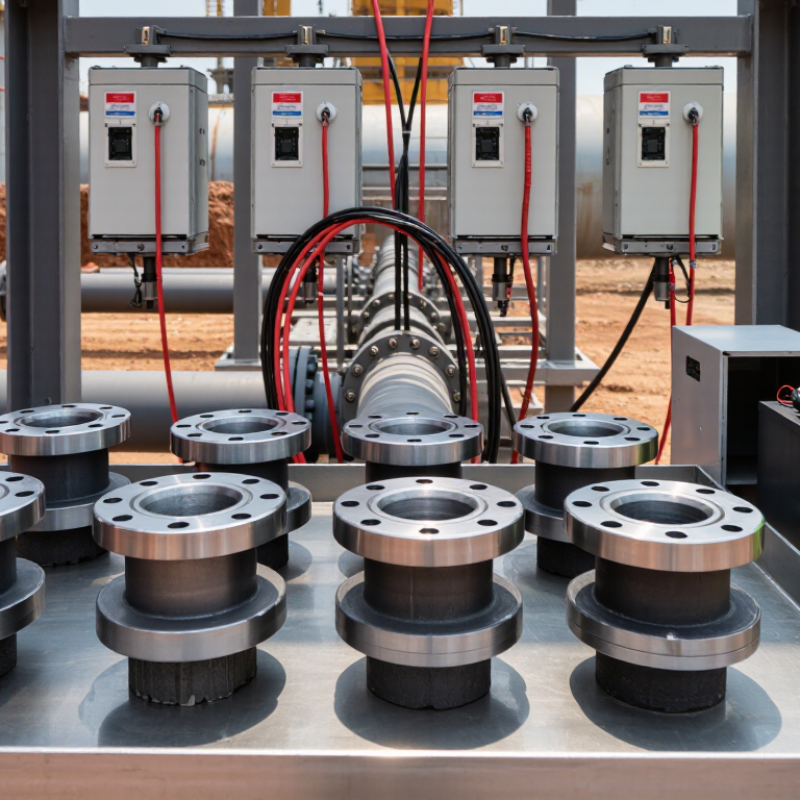
An impressed current anode sends protective direct current into the surrounding electrolyte, such as soil or seawater. A rectifier supplies the current, while cables connect the anode and the protected metal structure. The structure receives electrons and becomes the cathode. This helps slow corrosion at exposed areas, including coating scratches and pipe joints. The anode itself is part of an electrical system, not a protective coating.
Current needs a complete circuit and a suitable path through the electrolyte. An engineer selects anode material, placement, and output based on factors such as soil resistivity, water conditions, structure size, and coating condition. Poor placement can create uneven protection: a nearby section may receive too much current while a distant section receives too little. Real sites rarely match every design assumption. Measurements and adjustments matter.
Tips: Check rectifier readings and cable connections during routine inspections. Compare structure-to-electrolyte potentials at several test points, not just beside the anode. Look for damaged insulation, loose terminals, or unexpected output changes. Small details matter. Keep measurement records, and have a qualified corrosion professional review unusual readings; one reading alone may not explain the whole system.
How Impressed Current Anode Systems Work
An impressed current cathodic protection system uses an external DC power source to control corrosion on a buried or submerged structure. The rectifier’s positive lead connects to an anode, often installed in a prepared groundbed. Its negative lead connects to the steel being protected. Current travels through the surrounding soil or water toward the structure. The system supplies electrons to the steel, helping reduce its tendency to corrode. It is not magic.
The anode does not protect every surface equally by itself. Coating condition, soil resistivity, anode spacing, and electrical continuity all affect current distribution. For example, a long pipeline may need several test stations and carefully positioned anodes. A reference electrode measures the structure’s electrical potential, while technicians adjust the rectifier output and check readings over time. Too much current can damage coatings or affect nearby metal, so higher output is not automatically better.
Field readings can look tidy while a poorly placed anode leaves a shaded section underprotected. That is why design assumptions need checking against site measurements. Soil conditions may vary within a short distance, and connections can loosen or degrade. Regular inspections help reveal these changes, though no single reading tells the whole story. An effective system depends on sound installation, sensible monitoring, and adjustments based on actual conditions.
An impressed current cathodic protection (ICCP) system uses a DC rectifier to drive current from an anode, through the electrolyte, to the structure being protected. A reference electrode helps monitor structure-to-electrolyte potential.
How to read this chart: The illustrative points show a plausible example in which increased DC output current shifts the measured steel potential more negative. Actual readings depend on the structure, anode placement, electrolyte, and measurement method; they are not design or acceptance criteria. Protection criteria should be assessed using the applicable standard and reference electrode.
Mixed-metal-oxide (MMO) coated titanium is a common impressed-current anode for buried structures and water tanks. Its titanium core conducts current, while the oxide coating provides the active surface. It is compact and generally consumes little anode material, but coating life depends on current density, electrolyte, and installation quality. Small defects matter.
High-silicon cast iron offers a sturdy, comparatively economical option, especially in soil installations with carbonaceous backfill. It is heavy, and its output depends strongly on the surrounding backfill and soil resistivity. Graphite is also used with backfill, but it is brittle; rough handling can crack it before commissioning. Platinized titanium can deliver high output from a small surface, though coating condition and operating limits require close attention.
AMPP’s 2016 IMPACT study estimated corrosion costs at US$2.5 trillion annually, about 3.4% of global GDP. That figure covers corrosion broadly, not anode performance. For selection, engineers should compare measured soil resistivity, design current demand, anode current density, and expected service life. ISO 15589-1:2015 provides a framework for pipeline cathodic-protection design, while project-specific testing remains essential. A tidy datasheet cannot replace a field survey.
The best impressed-current anode depends on the structure, surrounding electrolyte, and protection target. Start with a site survey. Measure soil resistivity, map the structure, and check coating condition. These details help estimate current demand and identify where current may distribute unevenly. A large rectifier cannot fix a poorly located anode bed.
For shallow groundbeds, mixed-metal-oxide-coated titanium anodes may suit compact layouts. High-silicon cast-iron anodes are also used in groundbeds, often with carbonaceous backfill. Neither option is universally best. Consider operating current, expected service life, electrolyte chemistry, installation access, and replacement difficulty. Small details matter. A wet, low-resistivity site can behave very differently from dry, resistive soil, even when the steel area looks similar.
NACE International’s 2016 IMPACT study estimated corrosion’s global cost at US$2.5 trillion annually, or 3.4% of global GDP. It also reported that corrosion-control practices could save 15–35% of those costs. This broad estimate is not a promise of savings from an anode alone. Still, it supports careful design rather than choosing by purchase price. Compare lifecycle cost, and verify the design through commissioning measurements. One uncertainty remains: field conditions can change, so monitoring should inform adjustments over time.
A dependable impressed-current anode system begins with careful installation. Confirm the anode location, cable route, and electrical connections against the approved design before backfilling or closing access points. Keep connections dry and protected, and avoid damaging the anode coating during handling. In a groundbed, suitable spacing and backfill help distribute current; the exact arrangement depends on soil or water conditions. Small details matter.
After energizing the system, record rectifier voltage and current, then measure structure-to-electrolyte potentials with a suitable reference electrode. Take readings at repeatable locations and note operating conditions, including nearby electrical activity where relevant. Compare results with the project’s protection criteria rather than relying on one attractive reading. Numbers can drift. If readings change unexpectedly, inspect connections, cables, reference-electrode condition, and current distribution before increasing output.
Anode service life is not a fixed calendar promise. It depends on anode material, operating current, environment, and the total charge the design expects the anode to deliver. Keep a dated monitoring log, review trends, and investigate rising output or declining protection levels. In practice, measurements are not always tidy; access, weather, and equipment can complicate comparisons. Document those limits, and have a corrosion professional assess unusual results before making system adjustments.
| Anode Type | Typical Applications | Installation Considerations | Monitoring and Maintenance | Indicative Service-Life Planning |
|---|---|---|---|---|
| Mixed-metal-oxide-coated titanium | Buried pipelines, tank bottoms, reinforced concrete, and seawater systems, subject to anode design and electrolyte conditions. | Available as wire, ribbon, tubular, or mesh forms. Provide a suitable coke-breeze backfill for many groundbed installations; follow the coating supplier’s limits for current density and operating environment. | Check rectifier output, circuit continuity, groundbed resistance, and structure-to-electrolyte potentials. Investigate changes in output or potential rather than relying on rectifier readings alone. | Often designed for approximately 20–50 years, but actual life depends on coating type, current density, electrolyte, and operating conditions. |
| High-silicon cast iron | Deep or shallow groundbeds for pipelines, storage tanks, and other buried steel structures. | Install with the specified conductive backfill and maintain electrical isolation from unintended metallic paths. Deep groundbeds require appropriate casing, venting, and installation records. | Trend individual anode-string current where test facilities allow. Check rectifier performance, groundbed resistance, cable connections, and protection potentials during surveys. | Commonly planned for roughly 15–30 years; consumption and life vary with current output, soil conditions, and anode dimensions. |
| Graphite | Groundbeds for buried structures, particularly where the site conditions and system design are compatible with the material. | Handle carefully because the material is brittle. Use the specified backfill and installation procedure, and protect connecting cables and joints from moisture and mechanical damage. | Monitor current output, circuit resistance, and structure potentials. A gradual rise in resistance or declining output can indicate deterioration or connection problems. | Often planned for approximately 5–15 years, with substantial variation according to current density, moisture, backfill, and installation quality. |
| Platinized titanium or niobium | Specialized applications including seawater and other conductive electrolytes, when the selected substrate and coating are suitable for the service. | Confirm electrolyte chemistry, temperature, current density, and polarity limits before selection. Use compatible cable connections and avoid damage to the active coating during handling. | Measure anode output and structure potentials; inspect accessible connections and compare readings with commissioning baselines. Follow the design’s coating-specific operating limits. | Service life is coating- and application-dependent; design values commonly span about 10–25 years and must be confirmed for the intended operating conditions. |
Planning note: Service-life figures are indicative engineering ranges, not guarantees. Final anode selection and life calculations should account for design current, anode consumption or coating limits, electrolyte resistivity and chemistry, backfill, installation quality, and operating duty. Establish commissioning baselines and set survey intervals in the project’s cathodic-protection plan.
