
Choosing a Line Boring Machine is not simply a matter of selecting the largest model or the lowest price. The right machine must suit the repair, the workpiece, and the conditions at the job site. A portable unit may fit a damaged excavator linkage in the field, while a workshop setup may better handle larger components and repeat jobs. Measure twice.
Start by checking the bore diameter, required boring length, material, and available clearance. These details help determine the boring bar size, mounting method, and machine capacity. Also consider how the unit will be aligned and secured. A setup that shifts under load can affect the finished bore, even when the machine itself is well built. Access matters, too: guards, nearby structures, and awkward workpiece positions can make an otherwise suitable machine difficult to use.
Compare spindle speed, feed control, power requirements, and the availability of tooling and support. Ask suppliers for clear specifications, operating guidance, and examples relevant to your type of work. Verify important claims rather than relying on a product photograph or a broad capacity figure. If possible, review a demonstration or run a test on representative material. No checklist removes every uncertainty. Job conditions vary, and the first choice may not be perfect. A careful comparison, however, can reduce avoidable downtime and help you select a Line Boring Machine that fits both current repairs and realistic future needs.
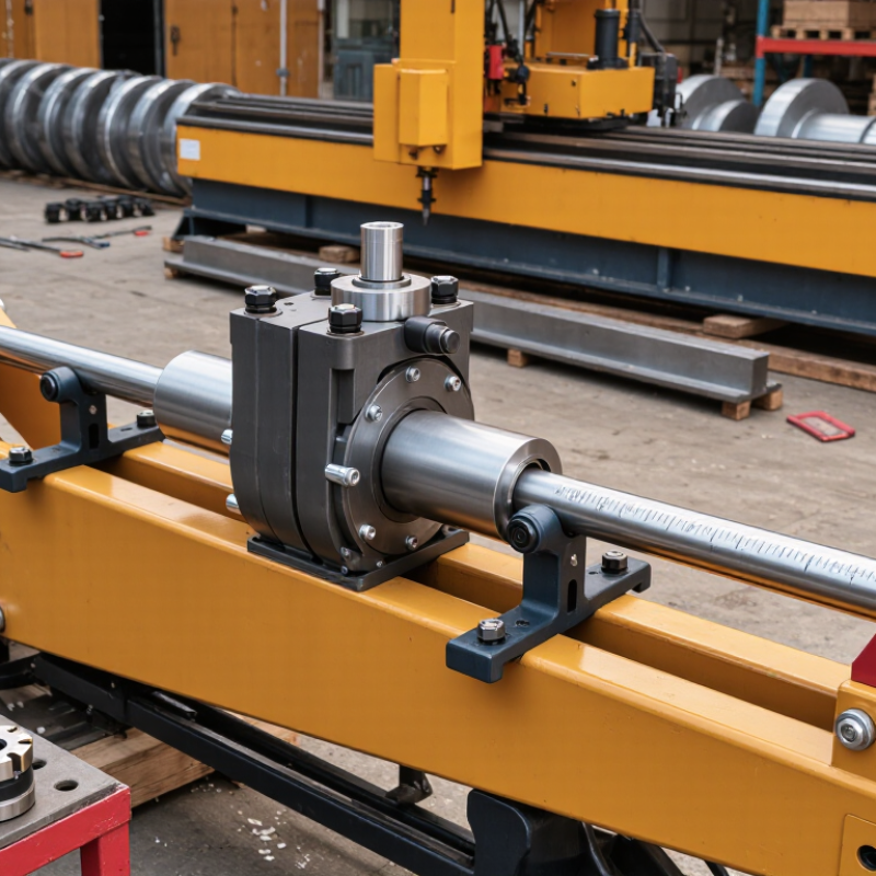
Before choosing a line boring machine, define the repair—not just the largest bore size. Record the damaged bore’s original diameter, required finished diameter, length, and location. Note the workpiece material and whether the bore is blind or passes through. These details affect bar length, cutting tools, and setup options. Measure carefully. A few millimeters of access can change which mounting arrangement will fit.
Set acceptance requirements before comparing machines. Specify the allowable diameter variation, surface finish, and alignment with nearby bores or shafts. Check whether the repair must happen in place, since removing a large component may be impractical. Also assess clearance for the boring bar, supports, power unit, and chip removal. A common planning mistake is focusing on diameter while overlooking setup space. The measurements may still be incomplete; verify critical dimensions on the actual workpiece.
Tips: Photograph the bore and surrounding structure, then sketch its dimensions and access limits. Ask the repair team to confirm tolerances and measurement methods. Keep a margin for tool reach and secure mounting. A machine that meets the nominal bore range may still be unsuitable if it cannot be aligned or supported safely.
These illustrative sample measurements show how bore diameter can vary across repair jobs. Before selecting a machine, measure each bore’s diameter and length, and record access constraints, alignment needs, and required tolerances. Confirm that the machine’s working range and setup meet the actual job requirements.
How to Choose a Line Boring Machine? Start with accurate measurements of the bore’s diameter and shape. Measure at several points, including both ends, because wear can make a hole slightly oval. Record the smallest and largest readings. A worn bore may need more cutting allowance than its nominal size suggests. That difference matters.
Next, measure the bore’s depth and note how much room surrounds the workpiece. The machine’s bar must reach the full length while staying aligned and adequately supported. Check for nearby walls, hoses, brackets, or other obstructions that could limit setup or tool movement. Also consider where the operator can safely position controls and inspect the cut. A tight access area can change the practical choice, even when the machine’s capacity looks suitable on paper. There is no universal allowance; the workpiece and repair plan matter.
Tips: Sketch the bore and surrounding clearance. Include diameter, depth, entry direction, and obstacles. Recheck measurements before ordering; even a small measuring error can create a poor fit. One detail is easy to miss: access for setup may be tighter than access for cutting.
| Job Example | Finished Bore Diameter | Bore Length / Depth | Workpiece Access to Measure | Machine Setup to Consider | Key Selection Check |
|---|---|---|---|---|---|
| Compact pivot or hinge bore | 25–50 mm (1.0–2.0 in) | 50–150 mm (2.0–5.9 in) | Check axial entry clearance at both ends, nearby brackets, and room for the drive unit. | Compact portable system with a short boring bar and rigidly mounted supports. | Confirm the machine’s minimum boring diameter and that the bar, cutter, and supports fit through the available opening. |
| Medium equipment pin bore | 50–150 mm (2.0–5.9 in) | 150–500 mm (5.9–19.7 in) | Measure the distance between bore faces and the radial clearance around the work area. | Portable line boring setup with adjustable support positions and a bar matched to the bore length. | Check the machine’s diameter range, bar working length, support spacing, and available feed travel. |
| Long articulated joint or linkage bore | 75–200 mm (3.0–7.9 in) | 500–1,000 mm (19.7–39.4 in) | Measure the full span between mounting faces and identify surfaces suitable for securing each support. | Long-bar configuration with multiple rigid support points where the machine design allows them. | Use the manufacturer’s permitted bar span and support arrangement; long unsupported spans can reduce cutting stability. |
| Large structural or heavy-equipment bore | 150–300 mm (5.9–11.8 in) | 300–800 mm (11.8–31.5 in) | Check access for the bar, bearing supports, drive head, and tools used to mount and align the machine. | Heavy-duty portable system with a bar and supports rated for the required diameter and cutting load. | Verify the machine’s maximum boring diameter, mounting capacity, available torque, and the workpiece’s mounting rigidity. |
| Restricted-access bore near surrounding components | Measure the actual bore; for example, 40–120 mm (1.6–4.7 in) | Measure the actual face-to-face distance; for example, 100–400 mm (3.9–15.7 in) | Record the smallest opening, side clearance, overhead clearance, and whether the bar can enter from either end. | Low-profile or modular configuration, selected to suit the available entry path and mounting locations. | Compare the complete setup envelope—not just the bar diameter—with the available space around the workpiece. |
| Multiple bores requiring alignment | Record the diameter of every bore; for example, 50–150 mm (2.0–5.9 in) | Measure each bore’s width and the center-to-center distance between bores. | Check whether one bar can pass through all bores and whether supports can be positioned without obstruction. | Through-bar setup with a suitable alignment method, such as a precision alignment mandrel or measurement system. | Define the required centerline alignment and tolerance before choosing the machine and setup method. |
Planning note: These figures are example job ranges, not universal machine limits. Measure the finished bore diameter, total bore length, entry openings, and mounting space, then confirm the required configuration against the machine’s published specifications.
Portable line boring machines suit repairs where a component cannot be removed easily. Their compact frames can fit between machine structures, but limited clearance may complicate setup. Access is tight. Check the distance between mounting points, available bar length, and room for the drive unit before choosing a model. A portable system is only useful if it can be aligned securely.
Stationary machines offer a more controlled setup for repeat work or larger components. They may provide steadier support and broader adjustment, but need floor space and a suitable workholding arrangement. Modular configurations sit between these options: operators can select bars, supports, and drive units to match different bore sizes. More parts can mean more setup choices—and more chances to misalign something. Keep it simple.
Compare feed control, speed adjustment, and measurement features against the material and bore condition. For example, a worn steel housing may need careful alignment and shallow passes, while a small repair may not justify a large machine. Ask how the machine handles interrupted surfaces and long bar spans. A specification sheet cannot show every awkward setup; measure the actual clearance twice, and confirm that supports can be fixed to sound surfaces.
Match the line boring machine to the largest bore and longest reach the job actually requires. Check bar length, cutting diameter, feed stroke, and available torque; a machine that barely reaches the repair may force awkward repositioning. Leave room for setup errors. Mud, rust, and a slightly misaligned bore can all add resistance, so rated capacity is not a comfortable working target. I would also check whether the frame can be anchored securely to the component, not just whether it fits through the access opening.
Site conditions can rule out an otherwise suitable machine. Measure the clear path to the work area, including doorways, overhead obstructions, and space for the power unit and hoses.
In a trench, OSHA’s excavation guidance requires safe egress for workers in trenches 4 feet or deeper, with no more than 25 feet of lateral travel to reach it. Keep machine placement from blocking that route. Noise matters too: NIOSH’s Criteria for a Recommended Standard: Occupational Noise Exposure sets an 85 dBA limit for an 8-hour time-weighted average. Plan for hearing protection and exposure time if nearby equipment is loud.
Before mobilizing, compare the workpiece dimensions with the machine’s setup range, then confirm power, clamping access, and tool clearance on site. A small mock-up helps. It will not catch every problem, but skipping it can cost more.
How to Choose a Line Boring Machine?
Choosing a line boring machine starts with the job, not the catalogue. Check the boring diameter, bar length, and access around the workpiece. In a repair bay, a machine may meet the specification yet leave too little room for its feed unit. Test the controls with gloves on. Can the operator adjust feed speed, stop motion, and read indicators without reaching across moving parts? Simple controls reduce hesitation, while adjustable settings help with varied repairs. Ask for repeatability data and a demonstration on comparable material.
Support matters after delivery. Confirm what training includes, how quickly technical help responds, and whether wear parts are readily available. A delayed bearing or missing cutter can leave a machine idle. Review mounting requirements, guards, emergency stops, and setup instructions. Match these provisions to your site procedures; a checklist cannot replace hands-on training. I still find setup time harder to predict than quoted cycle time. That deserves attention.
Tips: Compare ownership costs over several years, not purchase price alone. Include tooling, consumables, training, maintenance, downtime, and transport. Request a service schedule and prices for common replacement parts. Keep a sample-job log; actual feed rates and setup times may challenge your estimates. Leave room for uncertainty.
